Hard Drive pcbs play a crucial role in the seamless functioning of power distribution routes within electronic devices. These intricate boards efficiently route power from connectors to components, ensuring that each part receives the necessary voltage levels with the help of regulators. Additionally, PCBs manage data transfer between platters and computers, facilitating smooth communication between these vital elements. Their buffer function allows for the temporary storage of data during transfers, preventing potential loss or corruption. Moreover, PCBs are equipped with motor control capabilities that enable precise management of disk spin and head actuator movements, contributing to optimal performance. They also incorporate error detection mechanisms to check data integrity and request retransfers when necessary. Furthermore, PCBs provide SMART drive diagnostics reports which offer valuable insights into device health and performance metrics. This comprehensive range of functions illustrates the essential role that PCBs play in ensuring efficient operation and longevity of electronic devices.

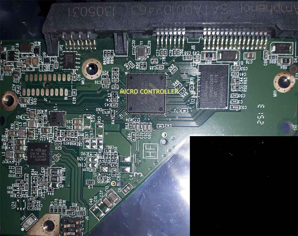
The MCU is in charge of overseeing the functions of your HDD. Its central processor and peripheral components together ensure that multiple tasks are carried out smoothly. Placed strategically on the PCB, the architecture of the MCU helps reduce signal paths and potential interference. The control area of the MCU is typically found near the center of most PCBs. At its heart, the central processor of the MCU consists of an ALU, a control unit, registers, and an instruction pipeline which work together seamlessly to manage operations.

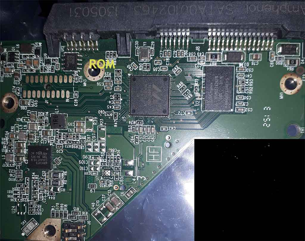
The ROM chip, if included, holds essential microcode for disk operations and cannot be modified by users. Manufacturers need to issue a separate update to change the contents of the ROM chip since it is embedded into the microchip during production. The firmware on the PCB communicates with the host computer to start up and maintain drive functionality. This programming is crucial as without it, the drive would not function properly. To ensure data persistence, ROM chips use non-volatile memory that retains stored data even after power loss.

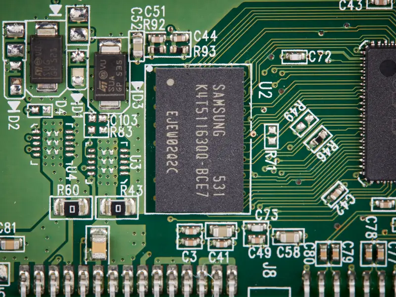
The cache is a microchip that stores a small amount of data and acts as a buffer between the mechanical components and the integrated circuits on the PCB.
In most models, the cache uses random-access memory (RAM) to hold frequently or recently accessed data. RAM is a high-speed storage option. Putting RAM on the PCB improves the drive’s responsiveness by reducing the need to retrieve data from the platters.
The cache size and organization depend on the manufacturer and model. In the case of the WD40EZRZ, the cache carries 64 megabytes of data. Some caches only store a few megabytes. Select models can hold several hundred megabytes.
The cache, or disk buffer, holds data while the MCU handles read and write requests. As the MCU works, the cache stores frequent data to better anticipate future requests. It also acts as a place for processed data to reside before being written to the platters.
Unlike the ROM chip, the cache is temporary storage. All of its data is cleared once the computer loses power or shuts down

An actuator arm is guided by the voice coil motor controller (VCM controller).
Since controlling the actuator arm requires multiple steps, the motor controller consumes most of the circuit board’s power.
Using the VCM controller, an electrical signal is generated and sent through the actuator coil to position the arm. As discussed above, this current interacts with a group of permanent magnets. By modifying the direction and magnitude of the current, the VCM controller alters the position of the actuator arm.
Sensors near the pivot point and optical encoders on the arm provide input to the VCM controller. Through continuous, closed-loop tracking algorithms, it compares the arm’s actual position to its desired position. This feedback influences the motor controller’s current generation. For precise movement and accurate positioning, control algorithms account for numerous variables, including inertia and rotational force.
Moreover, the VCM controller includes amplifiers, which increase the motor controller’s electrical signals to ensure the actuator coil’s current produces the desired effect.
Additionally, the VCM controller controls the platter spinning mechanism.
Motor contacts establish a reliable electrical connection between the PCB and the spindle motor.
Similar to head contacts, these contacts consist of a terminal on the PCB fastened to a corresponding point on the spindle motor. The connection provides control information and power to the motor. These signals determine when the motor starts or stops and set the speed of the spinning platters.
Follow the link for more about Data Recovery Perth
